CHALLENGE:
The utility is undergoing efforts to increase service reliability and reduce outage time for their customers fed by underground cable equipment. Padmount load break switches are used as sectionalizing points for the underground three phase circuits however the utility decided to incorporate single phase protection devices wherever single phase loads were tapped. Rating requirements were for both 15.5 and 27kV, 200A continuous current. Because much of the cable ran through residential areas, the utility wanted as small a vault as possible with top access to the equipment. They also wanted the capability to reset the device from above ground to quickly re-energize a faulted circuit.
SOLUTION:
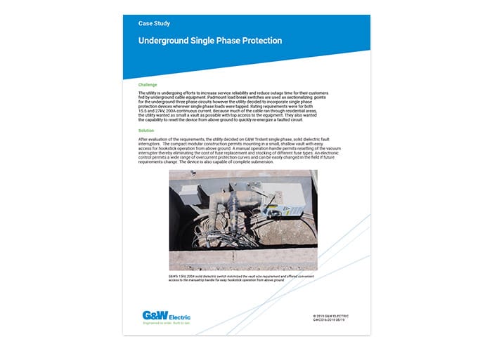
After evaluation of the requirements, the utility decided on G&W Electric Trident® single phase, solid dielectric fault interrupters. The compact modular construction permits mounting in a small, shallow vault with easy access for hookstick operation from above ground. A manual operation handle permits resetting of the vacuum interrupter thereby eliminating the cost of fuse replacement and stocking of different fuse types. An electronic control permits a wide range of overcurrent protection curves and can be easily changed in the field if future requirements change. The device is also capable of complete submersion.
FEATURES:
- High speed automatic transfer switching with overcurrent protection
- Distance between preferred and alternate sources is limited only by communication link selected.
- Communication can be via cable, fiber optic or wireless.
- Directional overcurrent protection
- Battery backup and sophisticated battery monitoring
- SCADA inputs/outputs
- DNP 3.0 available
- Total restoration time (using an Open before Close transition) in as little as 8 cycles*
- Verification of switch status before operation eliminates the possibility of paralleling sources
- User selection of transition sequence
- Complete events recorder with time/date stamp
- Delay timers for initial and return transfer
- Option for dead-line operation
*Communication devices and transfer delay timers will affect the total restoration time.
RATINGS:
Maximum Design Voltage, kV……………………………………..15.5………..29.2 ………..38
Impulse Level (BIL) kV……………………………………..110…………125………..150
Continuous and Load break Current, A ………………………….800 ………..800 ……….800
8 Hour Overload, A ……………………………………..960…………960 ……….960
Interrupting Current, kA rms sym. ……………………..12.5 ………..12.5………12.5
Making Current, rms asym. kA ……………………..20…………..20…………..20
Peak, asym. kA……………………32…………..32…………..32
Mechanical Endurance, Operations……………………….10,000 ……10,000 ..10,000
For more information:
Contact your local G&W Electric representative.
CONCLUSION:
If an overcurrent is detected on the load side of the system, the 351-R control will engage its overcurrent protection logic and override the automatic transfer sequence. This gives the user the benefits of both recloser overcurrent protection and high speed automatic source transfer in one package.
This solution simplifies the number and variety of distribution system components as well as providing a significant cost savings. It is one example of G&W’s pre-engineered LaZerTM family of automation solutions.