CHALLENGE:
The government of South Korea required more land for commercial and industrial growth. The preferred location selected for expansion however was occupied by a major U.S. military base. An agreement was reached between the U.S. and the local government to move the base about 100 km and combine it with a smaller, existing U.S. military installation. This turned out to be one of the largest U.S. military projects undertaken outside of the United States. A local South Korean firm was hired as the main contractor but several entities from the U.S. were involved in the design and approval process.
Expansion plans included new barracks, operations facilities, equipment storage, and a new airfield. To support the power needs of this expansion, a new infrastructure was designed to include a major upgrade of an existing substation and the addition of a new substation in a later phase. Because of the importance of this military installation, the decision was made to totally automate the distribution system to maximize power reliability. The preferred automation scheme was for a self-contained smart system which could automatically reconfigure itself to clear a fault and restore power without relying on communication and control from a remotely located master station.
Due to the size of the project and the aggressive timetable, construction was implemented in phases. The first phase involved dividing most of the base into four radial loop systems each incorporating 5-7 automated switches being fed from the existing substation. Future phases would require additional automated switches and a new substation.
Switches:
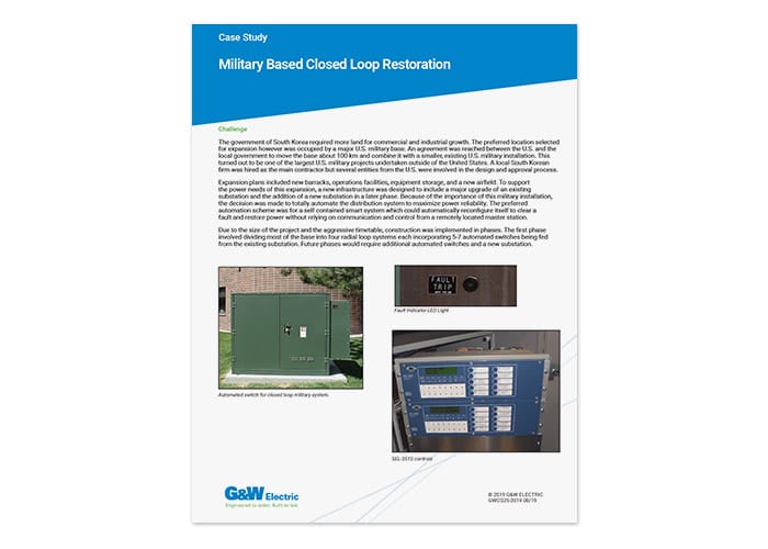
All seven switches were identical in design, providing ease of installation, maintenance or replacement, and operator familiarity. G&W Electric supplied SF6 and solid dielectric padmounted, four way style switches, with resettable fault interrupters and visible break switches on all four ways. Three power transformers were provided with each switch for control power and accurate voltage sensing for the protection scheme.
Switch Automation Package:
Schweitzer Engineering Laboratorie’s (SEL) relays were provided for maximum programming and communication functionality both now and in the future. G&W ELectric installed and programmed the relays and completely tested the communication between devices as well as the functionality of the system before shipment. One of the requirements of the application was that repair crews needed to be able to identify faulted cable sections from the road. G&W Electric provided fault indicators and indication from the SEL relays to activate a light on the side of the control enclosure to indicate that a fault had occurred on a section of cable.
Communication:
High speed communication was required for the fault isolation scheme. The protection scheme used was Permissive Overreaching Transfer Trip (POTT), which is a communication assisted means of tripping. The relays communicate with one another to identify the location of the fault and operate the fault interrupters to quickly isolate the faulted line section, maintaining power flow to all of the loads. Because a POTT scheme requires a high-speed means of communication, SEL Mirrored Bits™* protocol over fiber optic cable was used. The SEL relays were equipped with fiber optic transceivers for the protection communication circuit and built in fiber optic Ethernet ports for SCADA communication. By using Ethernet for remote SCADA access instead of serial communication, the Lazer solution offered engineering access to the relays so operators could modify settings from the control center, thereby eliminating the need to go to each individual automated switch.
Protection and Reconfiguration:
Sensing the direction of the fault required the G&W Electric switches to monitor voltage at both ends of all of the cable sections on the loop, as well as monitor the magnitude and phase angle of the voltage. Since these circuits were critical for base operations, several layers of protection were provided in the event the POTT scheme did not operate properly, including the use of directional elements in the relays, and standard time current coordination. While the switches are initially being used in a traditional single ended loop configuration, when all phases of the project are complete, they will be used in a fully automated closed loop fault isolation and reconfiguration scheme. In order to facilitate this, G&W Electric equipped the switches and relays so the customer can easily implement the closed loop scheme whenever they are ready.
The customer witnessed a Factory Acceptance Test at G&W Electric ’s Blue Island, Illinois USA headquarters. Because everything was fully tested before shipment, when the equipment arrived on site, commissioning required minimal time with no last-minute surprises. G&W also provided on-site training on the switches, relays, communication, programming, and parameters.
*MIRRORED BITS is a trademark of Schweitzer Engineering Laboratories, Inc
SOLUTION:
After much investigation, G&W Electric’s Lazer Automation Distribution system was selected. The Lazer system was comprised of seven automated padmount switches with SEL351S relays programmed to perform the required fault isolation. The solution met their current needs and provided the built-in capability to upgrade with minimal programming and no additional hardware.
The G&W Electric switches and SEL relays are time proven products known throughout the industry for their reliability and ease of use. The Lazer system was completely assembled, programmed, and tested by G&W Electric prior to shipment making it much easier for the contractor to install. The system was tailored by G&W to completely match the specific needs of the customer’s application. Representatives from G&W Electric were on site to test and commission the system as well as to provide operations training.