CHALLENGE:
A road expansion project mandated the removal of numerous overhead riser poles around a main thoroughfare. The surrounding area loads were fed by two separate 15kV circuits from the same substation but branching out into different directions. To minimize outage time and the number of
customers affected by a fault, 600A junction bars were designed into the distribution system to provide tap/disconnect points to isolate a faulted circuit. Junction bar locations were placed close to the end user load between longer cable runs utilizing multi-way load break switchgear. Junction bars were typically installed in small underground vaults which were subject to temporary submersion. This particular area had a history of nuisance circuit interruptions with no clear cause determined.
SOLUTION:
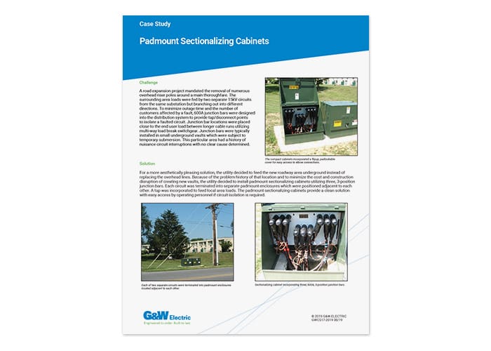
For a more aesthetically pleasing solution, the utility decided to feed the new roadway area underground instead of replacing the overhead lines. Because of the problem history of that location and to minimize the cost and construction disruption of creating new vaults, the utility decided to install padmount sectionalizing cabinets utilizing three, 3-position junction bars. Each circuit was terminated into separate padmount enclosures which were positioned adjacent to each other. A tap was incorporated to feed local area loads. The padmount sectionalizing cabinets provide a clean solution with easy access by operating personnel if circuit isolation is required.
FEATURES:
- High speed automatic transfer switching with overcurrent protection
- Distance between preferred and alternate sources is limited only by communication link selected.
- Communication can be via cable, fiber optic or wireless.
- Directional overcurrent protection
- Battery backup and sophisticated battery monitoring
- SCADA inputs/outputs
- DNP 3.0 available
- Total restoration time (using an Open before Close transition) in as little as 8 cycles*
- Verification of switch status before operation eliminates the possibility of paralleling sources
- User selection of transition sequence
- Complete events recorder with time/date stamp
- Delay timers for initial and return transfer
- Option for dead-line operation
*Communication devices and transfer delay timers will affect the total restoration time.
RATINGS:
Maximum Design Voltage, kV……………………………………..15.5………..29.2 ………..38
Impulse Level (BIL) kV……………………………………..110…………125………..150
Continuous and Load break Current, A ………………………….800 ………..800 ……….800
8 Hour Overload, A ……………………………………..960…………960 ……….960
Interrupting Current, kA rms sym. ……………………..12.5 ………..12.5………12.5
Making Current, rms asym. kA ……………………..20…………..20…………..20
Peak, asym. kA……………………32…………..32…………..32
Mechanical Endurance, Operations……………………….10,000 ……10,000 ..10,000
For more information:
Contact your local G&W Electric representative.
CONCLUSION:
If an overcurrent is detected on the load side of the system, the 351-R control will engage its overcurrent protection logic and override the automatic transfer sequence. This gives the user the benefits of both recloser overcurrent protection and high-speed automatic source transfer in one package.
This solution simplifies the number and variety of distribution system components as well as providing a significant cost savings. It is one example of G&W’s pre-engineered LaZerTM family of automation solutions.