CHALLENGE:
The vast majority of electrical service interruptions are on overhead circuits. Exposure to the elements, wildlife, and tree branches are all too common reasons why utilities implement solutions such as reclosers and automatic transfer controls to improve the inherent disturbances on overhead systems. Reclosers address transient problems while providing overcurrent protection.
Automatic transfer controls maintain power in the event of a permanent feeder problem (such as a downed conductor) by transferring the load and restoring power with an alternate utility source. But some critical loads require both source side automatic transfer and load side overcurrent protection.
SOLUTION:
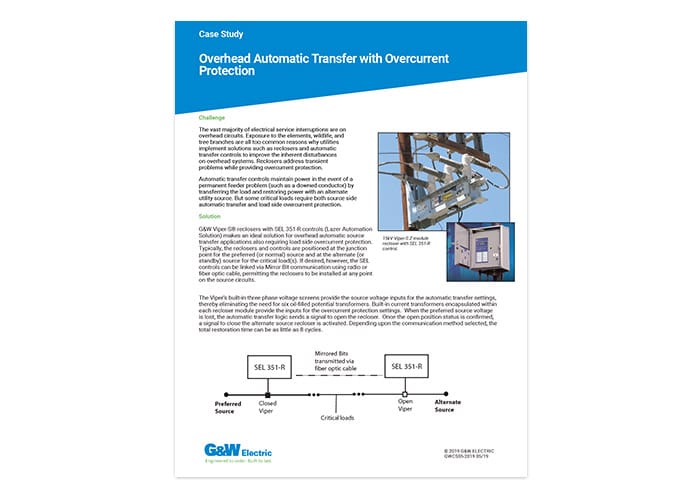
G&W Viper-S® reclosers with SEL 351-R controls (Lazer® Automation Solution) makes an ideal solution for overhead automatic source transfer applications also requiring load side overcurrent protection. Typically, the reclosers and controls are positioned at the junction point for the preferred (or normal) source and at the alternate (or standby) source for the critical load(s). If desired, however, the SEL controls can be linked via Mirror Bit communication using radio or fiber optic cable, permitting the reclosers to be installed at any point on the source circuits.
The Viper’s built-in three phase voltage screens provide the source voltage inputs for the automatic transfer settings, thereby eliminating the need for six oil-filled potential transformers. Built-in current transformers encapsulated within each recloser module provide the inputs for the overcurrent protection settings. When the preferred source voltage is lost, the automatic transfer logic sends a signal to open the recloser. Once the open position status is confirmed, a signal to close the alternate source recloser is activated. Depending upon the communication method selected, the total restoration time can be as little as 8 cycles.
FEATURES:
- High speed automatic transfer switching with overcurrent protection
- Distance between preferred and alternate sources is limited only by communication link selected.
- Communication can be via cable, fiber optic or wireless.
- Directional overcurrent protection
- Battery backup and sophisticated battery monitoring
- SCADA inputs/outputs
- DNP 3.0 available
- Total restoration time (using an Open before Close transition) in as little as 8 cycles*
- Verification of switch status before operation eliminates the possibility of paralleling sources
- User selection of transition sequence
- Complete events recorder with time/date stamp
- Delay timers for initial and return transfer
- Option for dead-line operation
*Communication devices and transfer delay timers will affect the total restoration time.
RATINGS:
Maximum Design Voltage, kV……………………………………..15.5………..29.2 ………..38
Impulse Level (BIL) kV……………………………………..110…………125………..150
Continuous and Load break Current, A ………………………….800 ………..800 ……….800
8 Hour Overload, A ……………………………………..960…………960 ……….960
Interrupting Current, kA rms sym. ……………………..12.5 ………..12.5………12.5
Making Current, rms asym. kA ……………………..20…………..20…………..20
Peak, asym. kA……………………32…………..32…………..32
Mechanical Endurance, Operations……………………….10,000 ……10,000 ..10,000
For more information: Contact your local G&W Electric representative.
CONCLUSION:
If an overcurrent is detected on the load side of the system, the 351-R control will engage its overcurrent protection logic and override the automatic transfer sequence. This gives the user the benefits of both recloser overcurrent protection and high-speed automatic source transfer in one package.
This solution simplifies the number and variety of distribution system components as well as providing a significant cost savings. It is one example of G&W’s pre-engineered LaZerTM family of automation solutions.