CHALLENGE:
A major midwest utility was experiencing a substantial number of outages on a ½ mile section of overhead feeder that runs through a heavily wooded forest preserve. Several large commercial
customers located on either side of the preserve had complained about the outages. Due to the size and density of the forest preserve, rerouting the line, bringing the feeder underground, or tree trimming were not economical options.
The existing feeder contained one G&W Electric Viper®-ST recloser with SEL 651R control and three manual disconnect switches. When a fault occurred, repair crews were dispatched to the site and
manually opened and closed the switches to isolate the faulted line section. This was a time-consuming process that frequently left customers without power for long periods of time.
The utility decided to address the problem. Their goal was to be able to clear a fault, isolate it if it was a permanent fault, and restore power to the customers in the shortest time possible. The utility was already familiar with and liked the Viper reclosers, so G&W Electric was called to help determine the best solution.
SOLUTION:
After a discussion with the utility, it was determined that the best solution would be a non-communicating, timing based, automatic loop restoration scheme. A non-communicating solution was preferred because:
- Radio communication was an issue due to the thick trees and line of site issues.
- Fiber was cost prohibitive.
- The operations crews had bad luck with a previous peer-to-peer loop scheme
The new scheme involved replacing the three manual switches with Viper-ST reclosers with SEL 651R controls and re-programming the existing Viper-ST.
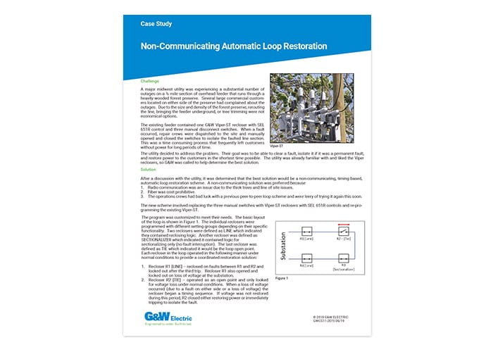
The program was customized to meet their needs. The basic layout of the loop is shown in Figure 1. The individual reclosers were programmed with different setting groups depending on their specific functionality. Two reclosers were defined as LINE which indicated they contained reclosing logic. Another recloser was defined as SECTIONALIZER which indicated it contained logic for sectionalizing only (no fault interruption). The last recloser was defined as TIE which indicated it would be the loop open point. Each recloser in the loop operated in the following manner under normal conditions to provide a coordinated restoration solution:
- Recloser R1 [LINE] – reclosed on faults between R1and R2 and locked out after the third trip. Recloser R1 also opened and locked out on loss of voltage at the substation.
- Recloser R2 [TIE] – operated as an open point and only looked for voltage loss under normal conditions. When a loss of voltage occurred (due to a fault on either side or a loss of voltage) the recloser began a timing sequence. If voltage was not restored during this period, R2 closed either restoring power or immediately tripping to isolate the fault.
- Recloser R3 [SECTIONALIZER] – was programmed to sense loss of voltage and to count the number of faults seen. On loss of voltage, R2 began a timing sequence that was coordinated with the time delay on R2 [TIE]. If R3 did not see any fault current, it automatically opened after the timing sequence indicating the fault was between R3 and R4. If it saw fault current and loss of voltage, it opened after two fault counts.
- Recloser R4 [Line] – reclosed on faults upstream and locked out after the third trip. R4 also opened and locked out on loss of voltage (like R1).
Additional logic was included to account for a fast curve tripping option and hot line tag for crew safety. The faceplates on all of the 651R controls were adapted to meet the utility’s standards with a few modifications to account for the automation scheme. This was done so repair and operations crews could save time by not having to learn a new faceplate layout.
RESULTS:
The scheme was fully tested and its operation witnessed by utility personnel at G&W Electric’s Bolingbrook, IL facility. It was installed, commissioned, and is in operation. The scheme is built on templates that are completely configurable, so the utility has the option of modifying the timing, the voltage level to begin the timing sequence, and the number of reclose attempts on the line reclosers. This scheme also allows for additional reclosers to be added or the open point to be changed with the same base program. The only configuring required would be to select which function the recloser will provide (LINE, TIE, SECTIONALIZER) and adjust the timing coordination.