Home / Underground Switchgear / Gas Insulated SF6 Switchgear / GRAM- Load Break Switching with Integral Ground Position
SF6 Switch

GRAM Load Break Switchgear

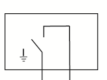
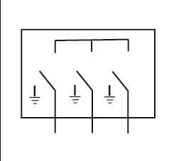
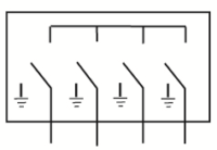
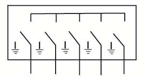
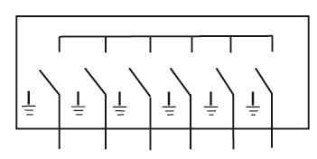
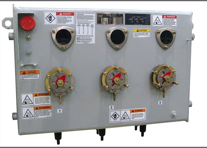
G&W Electric GRAM padmount and vault switchgear features load break switching capability with visible break and integral ground position in a totally sealed, submersible, dead front device. The integral ground position eliminates the need to handle any high voltage connections to ground the cable.  The switches are designed for use on 3-phase systems with voltages up to 38kV and 900A load break and continuous current. These switches are extremely flexible and are offered in many different styles. Switches are typically sold with the switch operators on the front side. The high voltage connections can be positioned on the bottom, top, or side to ease cable training and installation.

The switches are designed to IEEE C37.71 and C37.74 for load break capability. Padmount enclosures are designed and tested to IEEE C57.12.28 and C57.12.29. Explore how GRAM padmount and vault switchgear fits into our comprehensive switchgear solutions, delivering reliability and flexibility for diverse power distribution needs.

Features and Benefits

  • Construction Available compact construction with front accessible switch operators and bushings. Vault construction is also available with top or bottom bushings or top access to operators and bushings.

  • Ground Position Integral ground position on all ways to eliminate the need to handle high voltage components to ground the cable.

  • Automation Available for motor automation with portable or permanently mounted motor and controls. A variety of relays such as SEL, ABB, and GE are available with G&W Electric programming and cabinet construction. Cabinets can be ordered in a low voltage enclosure for padmount, pedestal or IP68 rated submersible for vault installed switchgear. Programming for automatic source transfer, or LaZer custom solutions are available.

  • Visible Break All ways are equipped with visible break to view the open, closed, and ground positions.

  • Voltage Sensing Available integral voltage sensing for use with voltage indication panel to determine in-phase condition or for use with a relay with up to 1% accuracy.

Configurations Chart for GRAM

# of WaysOne-line Diagram (Horizontal)Voltage Class (kV)Close Into Fault (kA asym)/strong>Catalog NumberApproximate
Width* in. (mm)Wt. w/SF6 lbs (kg)
2
1532GRAM21-376M-40RP29 (737)700 (318)
40GRAM21-376M-40PI32.5 (825)600 (270)
2532GRAM21-386M-40RP29 (737)700 (318)
40GRAM21-386M-40PI32.5 (825)600 (270)
3532GRAM21-396M-40RP29 (737)700 (318)
40GRAM21-396M-40PI32.5 (825)600 (270)
3
1532GRAM33-376M-40RP40.5 (1029)950 (431)
40GRAM33-376M-40PI62.25 (1580)1400 (635)
2532GRAM33-386M-40RP40.5 (1029)950 (431)
40GRAM33-386M-40PI62.25 (1580)1400 (635)
3532GRAM33-396M-40RP40.5 (1029)950 (431)
40GRAM33-396M-40PI62.25 (1580)1400 (635)
4
1532GRAM44-376M-40RP52 (1321)1200 (544)
40GRAM44-376M-40PI80.5 (2045)1800 (815)
2532GRAM44-386M-40RP52 (1321)1200 (544)
40GRAM44-386M-40PI80.5 (2045)1800 (815)
3532GRAM44-396M-40RP52 (1321)1200 (544)
40GRAM44-396M-40PI80.5 (2045)1800 (815)
5
1532GRAM55-376M-40RP63.5 (1613)2500 (1136)
40GRAM55-376M-40PI98.75 (2510)2200 (1000)
2532GRAM55-386M-40RP63.5 (1613)2500 (1136)
40GRAM55-386M-40PI98.75 (2510)2200 (1000)
3532GRAM55-396M-40RP63.5 (1613)2500 (1136)
40GRAM55-396M-40PI98.75 (2510)2200 (1000)
6
1532GRAM66-376M-40RP75 (1905)2600 (1182)
40GRAM66-376M-40PI117 (2970)2600 (1180)
2532GRAM66-386M-40RP75 (1905)2600 (1182)
40GRAM66-386M-40PI117 (2970)2600 (1180)
3532GRAM66-396M-40RP75 (1905)2600 (1182)
40GRAM66-396M-40PI117 (2970)2600 (1180)
For rotary puffer (RP): Tank depth= 25″ (635mm), Tank height = 27″ (686mm)
For linear puffer (PI): Tank depth= 34″ (865mm), Tank height = 32″ (815mm)
*Dimensions are approximate and do not include entrances, gauges, frames, or operators

Ratings Chart for GRAM

Voltage Class15kV25kV35kV
Maximum Design Voltage15.5kV27kV38kV
Impulse Level (BIL)110kV125kV150kV
One Minute Withstand35 AC kV60 AC kV70kV
One Minute Withstand, Protection Test Rating34 AC kV40 AC kV50kV
15 minute withstand53 DC kV78 DC kV103kV
** Continuous and load break current630 Amps630 Amps630 Amps
Momentary current40kA asym40kA asym40kA asym
* Fault-close current (3 times)40ka asym40ka asym40ka asym
One second current25kA asym25kA asym25kA asym
Mechanical endurance, operations200020002000
* Rating shown for Linear Puffer, Rotary Puffer limited to 32kA asym
** Available at 900Amps

For Accessories and additional options see the full catalog.

Need more information? Contact the rep in your area.